30th Oct: Lessons on wiring electrics
 The incident today when I lost power to the ballast pump and Tiller Pilot made me think about the best way to have the electrics wired. When I installed the electrics in Seatern I was hoping to use my Torqeedo 1003S outboard. The lighter weight of the electric outboard justified installing two 110Ah lead acid batteries, one being used inter alia to recharge the Torqeedo lithium-ion battery while I was under sail.
Original setup
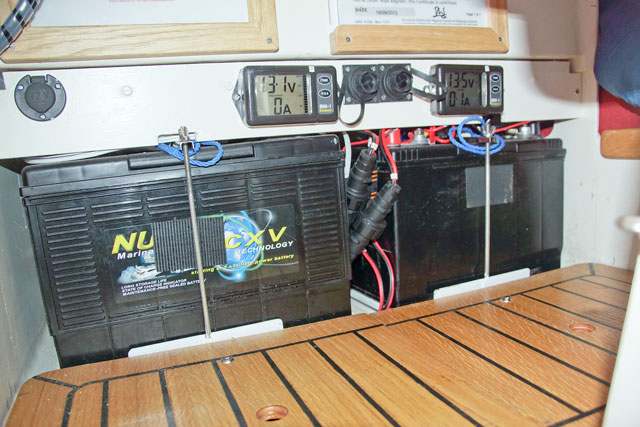
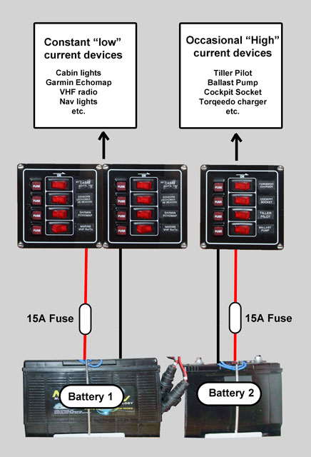
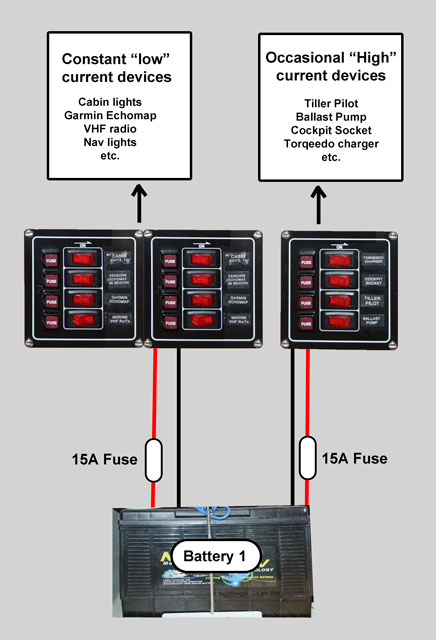
As shown in the photo each battery had a NASA battery monitor and was connected with plugs and sockets such that the roles of the batteries could be reversed, or everything powered from one battery only. While at my jetty, each battery had an Ctek charger to maintain its charge state. The set up is summarised in the diagram (right). Battery “1” supplied the low current devices which would be in use all the time, or for longer periods. Battery “2” supplied devices which might require large currents but on an intermittent basis, for example the electric ballast pump.
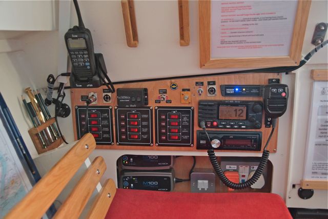
12/3/2014 Fuse panel, main electronic units are removable
Each individual device is fused and switched at the switch panel (resulting in eight switches being connected to battery “1” and four to battery “2”). In addition each battery, and the wires to the switch panel, are protected by a fuse close to the battery terminal. Those fuses guard against either the total demand from switched on devices being too great, or an otherwise catastrophic short circuit in the electronics panel wiring. (I should mention that I removed the ability of most of the switches to light up – the switch lights were consuming more power than the devices they switched!).
Present setup
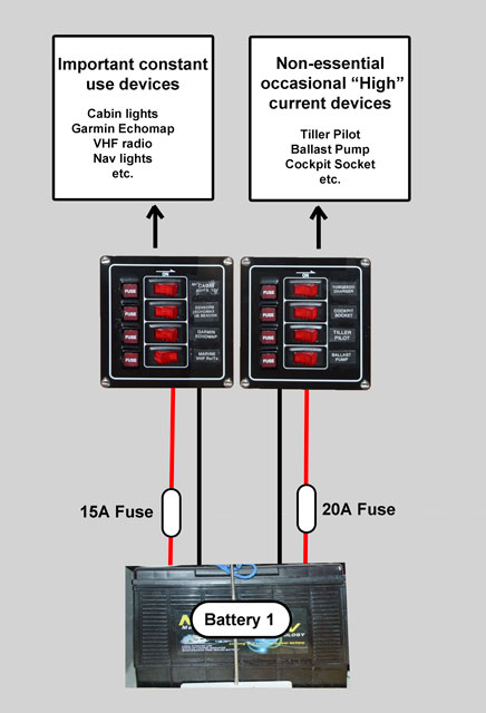
Unfortunately, the Torqeedo proved inadequate to power Seatern and I had to switch to a petrol outboard. To save weight I have removed one battery and used the facility I had originally installed to power all devices from a single battery. The resulting set up is shown by the diagram left. Today’s problem was due to the 15A fuse supplying the power for the “high” power devices being too small given the large current demand of the new “wakeboard” ballast pump during the short time it operates. The wire to the switchboard (4mm multistrand) would support 30A, so fitting a 20A fuse was a safe way to solve the problem.
It was only because I’d converted from two batteries that the “essential” nav aids (VHF, radar transponder, echo sounder etc.) were not lost when the ballast pump blew the fuse. However this made me realise that the best way to wire a single battery system would be something very similar to what I have. That is a separate fuse for the supply to “essential” devices so that they are independent of the other devices installed in the boat. This is schematically shown in the diagram. Probably everyone else knows this already!
 [Note added 5th Jan 2015: On the 29th December the fuse supplying the ballast pump and the tiller pilot blew again. I assume that the ballast pump impeller had become frozen overnight and the fuse did its job protecting the pump and the wiring. However that meant the Tiller Pilot didn’t work. Since the Tiller Tamer rope and pulley had also beome frozen (!) I had to heave to in order to reconnect the power to the pump and Tiller Pilot. It would be sensible to put the Ballast pump on its own fused supply since it is probably more likely to fuse than anything else – for example debris jamming the impeller.]